Electric Circuits Review
Navigate to:
Review Session Home - Topic Listing
Electric Circuits - Home || Printable Version || Questions with Links
Answers to Questions: All || #1-7 || #8-51 || #52-59 || #60-72
Part C: Diagramming and Analysis
 52. Consider the diagram at the right to answer the following questions.
a. If 4 Coulombs of charge flow past point A in 2 seconds, then ___ Coulombs of charge flow past point B in 2 seconds.
|
a. less than 4
|
b. 4
|
c. more than 4
|
|
d. impossible to make such a prediction without knowledge of the resistances.
|
b. If 4 Coulombs of charge flow past point A in 2 seconds, then ___ Coulombs of charge flow past point B in 1 second.
|
a. less than 4
|
b. 4
|
c. more than 4
|
|
d. impossible to make such a prediction without knowledge of the resistances.
|
c. If 4 Coulombs of charge flow past point A in 2 seconds, then ___ Coulombs of charge flow past point B in 4 seconds.
|
a. less than 4
|
b. 4
|
c. more than 4
|
|
d. impossible to make such a prediction without knowledge of the resistances.
|
d. If 4 Coulombs of charge flow past point A in 2 seconds, then ___ Coulombs of charge flow past point B in 4 seconds.
e. If 4 Coulombs of charge flow past point A in 2 seconds, then ___ Coulombs of charge flow past point C in 4 seconds.
f. Suppose that the resistance of the light bulb located between points A and B is increased. This would cause the current through the other light bulb to ____ (increase, decrease, remain the same).
|
Answer: See answers below.
This question tests your understanding of current as the rate at which charge (expressed here in Coulombs) flows past a point on a circuit. Current is found as the charge/time ratio. For a series circuit such as this one, the current is everywhere the same.
a. B; the current is 2.0 amperes at point A. To be the same 2.0 Amperes at point B, 4 Coulombs must pass the point in 2 seconds.
b. A; the current is 2.0 amperes at point A. To be the same 2.0 Amperes at point B, 2 Coulombs must pass the point in 1 second. In a lesser amount of time, less charge will flow past the point.
c. C; the current is 2.0 amperes at point A. To be the same 2.0 Amperes at point B, 8 Coulombs must pass the point in 4 seconds. In a greater amount of time, more charge will flow past the point.
d. 8; the current is 2.0 amperes at point A. To be the same 2.0 Amperes at point B, 8 Coulombs must pass point B in 4 seconds.
e. 8; the current is 2.0 amperes at point A. To be the same 2.0 Amperes at point B, 8 Coulombs must pass point C in 4 seconds.
f. decrease; increasing the resistance of a light bulb for a series of consecutive light bulbs will increase the overall resistance of the circuit and cause the current throughout the entire circuit to decrease.
|
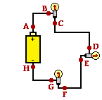 53. The diagram at the right shows three identical light bulbs wired in series. Several points along the circuit are labeled with letters. Compare the electric potential and the electric potential energy of the various points. For each comparison, use a greater than (>), less than (<), or approximately equal to (=) symbol.
|
Electric Potential
Comparison
|
Potential Energy
Comparison
|
|
VA = VB
|
PEA = PE B
|
|
VB > VC
|
PE B > PE C
|
|
VC = VD
|
PE C = PE D
|
|
VD > VE
|
PE D > PE E
|
|
VE = VF
|
PE E = PE F
|
|
VF > VG
|
PE F > PE G
|
|
VG = VH
|
PE G = PE H
|
|
VH < VA
|
PE H < PE A
|
|
Answer: See table above.
Point A corresponds to the positive terminal of the battery. At point A, charge possesses the greatest amount of electric potential energy. It has a high voltage at this location. In the process of moving through the circuit to the - terminal, the charge will have its electric potential energy converted to light energy (and heat energy) in the light bulbs. It will lose a portion of its electrical energy in each light bulb. The light bulb simply serves as an energy conversion device which transforms electric potential energy into non-electrical forms. As such, the potential energy (and thus the voltage) will drop in value every time the passes by a light bulb and reaches a point further from the high energy + terminal. Finally, at point H, all the electrical energy and voltage has been lost and the charge is in need of some energy input from the battery.
|
54. Use proper schematic symbols to construct a diagram of a circuit powered by a 6-Volt battery that consists of two 3-ohm resistors connected in series. Place ammeters in series at a location such that the current through each resistor can be measured and in a location such that the overall current in the circuit can be measured. On the schematic diagram, use an unbroken arrow to indicate the direction of conventional current. Finally, indicate the ammeter readings on the diagram.
|
Answer: See diagram below.
Since the two resistors are in series, the total or equivalent resistance is simply the sum of the individual resistances. The total resistance is 6 ohms. The total current in the circuit can be found by the ratio of battery voltage to total resistance:
ITOT =  VTOT / RTOT = (6 V) / (6 ohms) = 1 Amp VTOT / RTOT = (6 V) / (6 ohms) = 1 Amp
Since it is a series circuit, the current through the battery is the same as the current through each of the resistors.

|
[ #52 | #53 | #54 | #55 | #56 | #57 | #58 | #59 ]
55. Use proper schematic symbols to construct a diagram of a circuit powered by a 6-Volt battery that consists of two 3-ohm resistors connected in parallel. Place an ammeter in series with each of the individual resistors in a manner that the current through each resistor can be measured. Place a third ammeter in a location such that the overall current in the circuit can be measured. On the schematic diagram, use an unbroken arrow to indicate the direction of conventional current. Finally, indicate the ammeter readings on the diagram.
|
Answer: See diagram below.
The voltage across each branch is equivalent to the voltage of the battery. The current through a branch is simply the V/R ratio where V = 6 Volts and R = 3 ohms. This calculation leads to the conclusion that 2 Amps is the current in each branch. The current outside the branches is simply the sum of the current in the branches. So there will be a current of 4 Amps outside the branches.
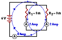
As an alternative to this solution, the equivalent resistance could first be determined using the 1/RTot equation for parallel circuits. The equivalent resistance is 1.5 Ohms. Once determined, the total circuit current can be calculated using ITot = VTot / RTot. The total circuit current would be 4 Amps. Then divide the 4 Amps into two equal branch currents to determine the current at each of the individual resistors.
|
[ #52 | #53 | #54 | #55 | #56 | #57 | #58 | #59 ]
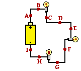 56. Consider the diagram at the right of a series circuit. Each light bulb in the circuit has an identical resistance. Use the labeled points on the diagram to answer the following questions. Each question may have one, less than one, or more than one answer.
a. The electric potential at point A is the same as the electric potential at point(s) B. Include all that apply, if any apply.
b. The electric potential at point C is the same as the electric potential at point(s) D and E. Include all that apply, if any apply.
c. The electric potential at point F is the same as the electric potential at point(s) G. Include all that apply, if any apply.
d. The electric potential at point I is the same as the electric potential at point(s) H. Include all that apply, if any apply.
e. The electric potential difference between points A and B is the same as the electric potential difference between points C and D (and C and E; and D and E; and F and G; and H and I). Include all that apply, if any apply.
f. The electric potential difference between points A and C is the same as the electric potential difference between points E and F (and C and F; and D and F; and E and G; and C and G; and D and G; and G and H; and F and H; and G and I; and F and I). Include all that apply, if any apply.
g. The electric potential difference between points A and F is the same as the electric potential difference between points E and H (and between any other two sets of points that are on the opposite side of two adjacent bulbs ... such as points C and H or points D and H or points E and I, etc.). Include all that apply, if any apply.
h. The electric potential difference between points D and H is the same as the electric potential difference between points A and F (and between any other two sets of points that are on the opposite side of two adjacent bulbs ... such as points C and H or points D and I or points E and I, etc.). Include all that apply, if any apply.
i. The current at point A is the same as the current at point(s) C (and at every other point on the circuit). Include all that apply, if any apply.
j. The current at point E is the same as the current at point(s) F (and at every other point on the circuit). Include all that apply, if any apply.
k. The current at point G is the same as the current at point(s) G (and at every other point on the circuit). Include all that apply, if any apply.
|
Answer: See answers above.
In an electric circuit, the electric potential for a moving charge is gained in the battery and lost in a light bulb (or some resistor found in the external circuit). So the electric potential of a charge is the same for any two points which are not separated by a battery or by a light bulb. (a through d)
In this circuit, the light bulbs have the same resistance; thus, each light bulb causes the same drop in potential (electric potential difference). So the electric potential difference will be the same between any two points which are distanced by a light bulb, or by two light bulbs. (e through h)
Finally, in a series circuit the current is the same at every point along the circuit. Since charge is conserved and since there is no location in a circuit where the charge is accumulating, there must be the same charge flow rate at all locations. (i through k)
|
[ #52 | #53 | #54 | #55 | #56 | #57 | #58 | #59 ]
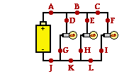 57. Consider the diagram at the right of a parallel circuit. Each light bulb in the circuit has an identical resistance. Use the labeled points on the diagram to answer the following questions. Each question may have one, less than one, or more than one answer.
a. The electric potential at point A is the same as the electric potential at point(s) B (and at any other point before the light bulbs ... such as at points C, D, E and F). Include all that apply, if any apply.
b. The electric potential at point D is the same as the electric potential at point(s) B (and at any other point before the light bulbs ... such as at points A, C, E and F). Include all that apply, if any apply.
c. The electric potential at point J is the same as the electric potential at point(s) K (and at any other point after the light bulbs ... such as at points G, H, I, and L. Include all that apply, if any apply.
d. The electric potential difference between points A and J is the same as the electric potential difference between points B and K (and any other combination of two points located on opposite sides of the light bulbs ... such as points A and K, or points A and L, or points F and G, or points D and G, etc., etc.). Include all that apply, if any apply.
e. The electric potential difference between points D and G is the same as the electric potential difference between points A and J (and any other combination of two points located on opposite sides of the light bulbs ... such as points A and K, or points A and L, or points F and G, or points E and H, etc., etc.). Include all that apply, if any apply.
f. The current at point A is the same as the current at point(s) J. Include all that apply, if any apply.
g. The current at point B is the same as the current at point(s) K. Include all that apply, if any apply.
h. The current at point C is the same as the current at point(s) L (and points F and I and E and H and D and G). Include all that apply, if any apply.
i. The current at point D is the same as the current at point(s) G (and at points F and I and C and E and H). Include all that apply, if any apply.
j. If the light bulb located between points D and G were to be replaced by a bulb of greater resistance, then the current at point(s) A, D, G, and J would be decreased. Include all that apply, if any apply.
k. If the light bulb located between points D and G were to be replaced by a bulb of greater resistance, then the electric potential difference between points -- and -- would be increased. Include all that apply, if any apply. (None apply.)
l. If the light bulb located between points D and G were to go out, then the current would decrease at point(s) A, D, G and J. Include all that apply, if any apply.
|
Answer: See answers above.
In an electric circuit, the electric potential for a moving charge is gained in the battery and lost in a light bulb (or some resistor found in the external circuit). So the electric potential of a charge is the same for any two points which are not separated by a battery or by a light bulb. Even if the circuit is a parallel circuit, any point between the positive terminal of a battery and light bulb will have the same electric potential; and any point located between the - terminal of the battery and a location after passage through the resistor of a branch have the same electric potential. (a through e)
In this circuit, the light bulbs have the same resistance. Thus, when charge reaches the branching location an equal amount of charge will chose the middle branch as does the left branch and the right branch. So with the same resistance, the current in every branch is the same. And the current prior to the branching location and after the branches come together is the same. Finally, locations B and K are at locations where current for two of the three branches will be passing; these points will have the same current. (e through i)
In j, removing the bulb in the first branch will not affect the current in the other branches. Such a modification will only reduce the overall circuit current. Less branches would result in more overall resistance and less overall current. Yet the current through the second branch is still the voltage drop across the second branch (which is the battery voltage) divided by the resistance of the second branch. Since removing the bulb in the first branch does not alter either quantity, the current in the middle branch is not altered.
In k, the electric potential across a branch is simply equal to the voltage of the battery. Removing a light bulb will not alter the voltage of the battery. Thus, there is no effect.
In l, if the light bulb in the first branch burns out, the same effect will occur as occurred in part j.
|
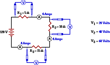
58. Consider the diagram below of a series circuit. For each resistor, use arrows to indicate the two locations where one would have to tap with the leads of a voltmeter in order to measure the voltage drop across the individual resistor. Finally, indicate the ammeter readings and the voltage readings.
|
Answer: See diagram above.
The total resistance (or equivalent resistance) can first be determined using the equation for series circuits.
RTot = R1 + R2 + R3 = 5 Ohms + 10 Ohms + 15 Ohms = 30 Ohms
Once known, the RTot value can be used with the battery voltage (ΔVTot) to determine the total current in the circuit.
ITot = (ΔVTot) / (RTot) = (120 V) / (30 Ohms) = 4 Amps
For a series circuit, the current through each resistor is the same as the total circuit current. Thus, I1 = I2 = I3 = 4 Amps.
The voltage drop across a resistor can be determined with a voltmeter by tapping with the leads on the metal wires on the opposite sides of the resistor. By so doing, the voltmeter determines the difference in voltage (i.e., voltage drop or electric potential difference) between the two locations where the leads were tapped. In this circuit, the expected voltage drops (ΔV1, ΔV2, and ΔV3 ) can be computed by determining the IR product for each resistor. This is shown below.
ΔV1 = I1 • R1 = (4 Amps) • (5 Ohms) = 20 Volts
ΔV2 = I2 • R2 = (4 Amps) • (10 Ohms) = 40 Volts
ΔV3 = I3 • R3 = (4 Amps) • (15 Ohms) = 60 Volts
|
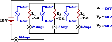
59. Consider the diagram below of a parallel circuit. For each resistor, use arrows to indicate the two locations where one would have to tap with the leads of a voltmeter in order to measure the voltage drop across the individual resistor. Finally, indicate the ammeter readings and the voltage readings.
|
Answer: See diagram above.
The total resistance (or equivalent resistance) can first be determined using the equation for series circuits.
1 / RTot = 1 / R1 + 1 / R2 + 1 / R3 = 1 / (5 Ohms + 1 / (10 Ohms) + 1 / (15 Ohms)
RTot = 2.727 Ohms
Once known, the RTot value can be used with the battery voltage (ΔVTot) to determine the total current in the circuit.
ITot = (ΔVTot) / (RTot) = (120 V) / (2.727 Ohms) = 44.0 Amps
The voltage drop across a resistor can be determined with a voltmeter by tapping with the leads on the metal wires on the opposite sides of the resistor. By so doing, the voltmeter determines the difference in voltage (i.e., voltage drop or electric potential difference) between the two locations where the leads were tapped. For a series circuit, the expected voltage drop across each resistor (ΔV1, ΔV2, and ΔV3 ) is the same as the total voltage drop. Thus, ΔV1 = ΔV2 = ΔV3 = 120 Volts.
In this circuit, the branch currents can be computed by using the ΔV = I•R equation for each resistor. This is shown below.
R1 = ΔV1 / R1 = (120 Volts) / (5 Ohms) = 24 Amps
I2 = ΔV2 / R2 = (120 Volts) / (10 Ohms) = 12 Amps
I3 = ΔV3 / R3 = (120 Volts) / (15 Ohms) = 8 Amps
|
Navigate to:
Review Session Home - Topic Listing
Electric Circuits - Home || Printable Version || Questions with Links
Answers to Questions: All || #1-7 || #8-51 || #52-59 || #60-72
You Might Also Like ...
Users of The Review Session are often looking for learning resources that provide them with practice and review opportunities that include built-in feedback and instruction. If that is what you're looking for, then you might also like the following:
- The Calculator Pad
The Calculator Pad includes physics word problems organized by topic. Each problem is accompanied by a pop-up answer and an audio file that explains the details of how to approach and solve the problem. It's a perfect resource for those wishing to improve their problem-solving skills.
Visit: The Calculator Pad Home | Calculator Pad - Electric Circuits
- Minds On Physics the App Series
Minds On Physics the App ("MOP the App") is a series of interactive questioning modules for the student that is serious about improving their conceptual understanding of physics. Each module of the series covers a different topic and is further broken down into sub-topics. A "MOP experience" will provide a learner with challenging questions, feedback, and question-specific help in the context of a game-like environment. It is available for phones, tablets, Chromebooks, and Macintosh computers. It's a perfect resource for those wishing to refine their conceptual reasoning abilities. Part 4 of the series includes topics in Electric Circuits.
Visit: MOP the App Home || MOP the App - Part 4