Light Waves and Color Review
Navigate to:
Review Session Home - Topic Listing
Light Waves and Color - Home || Printable Version || Questions with Links
Answers to Questions: All || #1-#11 || #12-#20 || #21-#28
Part B: Diagramming, Analysis, Calculations
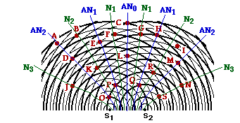
 21. Two point sources are vibrating together (in phase) at the same frequency to produce a two-point source interference pattern. The diagram at the right depicts the two-point source interference pattern. The crests are represented by thick lines and the troughs by thin lines. Several points on the pattern are marked by a dot and labeled with a letter. Use the diagram to answer the following questions.
a. Which of the labeled points are antinodal points?
b. Which of the labeled points are nodal points?
c. Which of the labeled points are formed as a result of constructive interference?
d. Which of the labeled points are located on the central antinodal line?
e. Which of the labeled points are located on the first antinodal line?
f. Which of the labeled points are located on the second antinodal line?
g. Which of the labeled points are located on the third antinodal line?
h. Which of the labeled points are located on the first nodal line (using the notation that the first nodal line is the nodal line directly to the left or the right of the central antinodal line)?
i. Which of the labeled points are located on the second nodal line (using the notation that the second nodal line is the second nodal line directly to the left or the right of the central antinodal line)?
j. Which of the labeled points are located on the third nodal line (using the notation that the third nodal line is the third nodal line directly to the left or the right of the central antinodal line)?
|
Answers: See diagram above for a visual representation of many of the answers.
a. ACDEHLMOPQ are all antinodal points which lie on antinodal lines. They are formed as a result of either a crest meeting a crest (two thick lines) or a trough meeting a trough (two thin lines). At the moment in time depicted in the diagram, point A is not a crest-crest or a trough-trough interference point. However, as time progresses and the circular waves continue their motion outwards from the source, point A (and all points on the antinodal lines) will be locations of crest-crest (or trough-trough) interference. At some instant in time, all points falling upon antinodal lines will be locations of constructive interference.
b. BFGJKNRS are all nodal points. They are formed as a result of a crest (thick line) meeting a trough (thin line).
c. CDEHLMOPQ (and possibly A) are all formed by constructive interference. They are all antinodal points and as such, they are the result of constructive interference. Point A is certainly not an antinodal point; however it is likely the result of constructive interference - two waves meeting with their displacement in the same direction (just not two crests or two troughs).
d. CL are on the central antinodal line. The central antinodal line is marked on the diagram above as AN0. It is the line which extends from the midpoint of the line connecting the two sources.
e. EHPQ are on the first antinodal line. They lie on the first antinodal line to the left or right of the central antinodal line. See diagram above.
f. ADMO are on the second antinodal line. They lie on the second antinodal line to the left or right of the central antinodal line. See diagram above.
g. There is no third antinodal line. See diagram above.
h. FG are on the first nodal line. They lie on the first nodal line to the left or right of the central antinodal line. See diagram above.
i. BKR are on the second nodal line. They lie on the second nodal line to the left or right of the central antinodal line. See diagram above.
j. JNS are on the third nodal line. They lie on the third nodal line to the left or right of the central antinodal line. See diagram above.
|
[ #21 | #22 | #23 | #24 | #25 | #26 | #27 | #28 ]
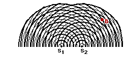
 22. Consider the interference pattern at the right. (The crests are represented by thick lines and the troughs by thin lines.) If the distance from S1 to point A is 49.5 cm and the distance from S2 to point A is 60.5 cm, then what is the wavelength?
|
Answer: W = 11.0 cm
Given: S1A = 49.5 cm and S2A = 60.5 cm and m=1 (the point is on the first antinodal line to the right of center)
Find: W (wavelength)
Strategy: Find the path difference (PD) from the two distances and then use the PD = m • W equation to calculate the wavelength.
PD = | S2A - S1A | = | 60.5 cm - 49.5 cm | = 11.0 cm
Now substitute into the path difference-wavelength equation and solve for wavelength (W):
11.0 cm = 1 • W
W = 11.0 cm
An alternative strategy involves recognizing from the diagram that point A is a distance of 4.5 wavelengths from point S1. Thus, the distance 49.5 cm equals 4.5 • W. Solving for W yields 11.0 cm. The same strategy can be used for the distance from S2 to point A, yielding the same answer.
|
[ #21 | #22 | #23 | #24 | #25 | #26 | #27 | #28 ]
 23. Consider the interference pattern at the right. (The crests are represented by thick lines and the troughs by thin lines.) If the distance from S1 to point B is 50.4 cm and the distance from S2 to point A is 34.5 cm, then what is the wavelength?
|
Answer: 6.28 cm
Given: S1B = 50.4 cm and S2B = 34.5 cm and m=2.5 (the point is on the third nodal line to the right of center)
Find: W (wavelength)
Strategy: Find the path difference (PD) from the two distances and then use the PD = m • W equation to calculate the wavelength.
PD = | S2B - S1B | = | 34.5 cm - 50.4 cm | = 15.7 cm
Now substitute into the path difference-wavelength equation and solve for wavelength (W):
15.7 cm = 2.50 • W
W = 6.28 cm
An alternative strategy involves recognizing from the diagram that point B is a distance of 8 wavelengths from point S1. Thus, the distance 50.4 cm equals 8 • W. Solving for W yields 6.28 cm. The same strategy can be used for the distance from S2 to point B, yielding the same answer.
|
[ #21 | #22 | #23 | #24 | #25 | #26 | #27 | #28 ]
24. Two point sources are vibrating in phase to produce an interference pattern. The wavelength of the waves is 7.60 cm. Point C is a point on the third nodal line. The distance from S1 (the nearest source) to point C is 65.6 cm. Determine the distance from S2 to point C.
|
Answer: 84.6 cm
Given: S1C = 65.6 cm and W = 7.60 cm and m=2.50 (third nodal line)
Find: S2C
Strategy: Find the path difference (PD) using the equation PD = m • W. The path difference signifies the difference in distance from the sources to the nearest point. The S2C distance is larger than the S1C distance by an amount equal to the path difference.
First find the path difference:
PD = m • W = 2.50 • 7.60 cm = 19.0 cm
Now add the path difference to the S1C distance to determine S2C.
S2C = S1C + PD = 65.6 cm + 19.0 cm = 84.6 cm
|
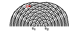
 25. Consider the interference pattern at the right. (The crests are represented by thick lines and the troughs by thin lines.) The distance from S1 to point D is 47.2 cm. What is the wavelength? What is the distance from S2 to point D? (HINT: Use the diagram.)
|
Answer: wavelength = 7.87 cm; S2D = 59.0 cm
Given: S1D = 47.2 cm and m = 1.50 (the second nodal line to the left of the central antinodal line)
Find: W and S2D
Strategy: Since neither a wavelength or a path difference is given or implicitly stated, the diagram will have to be used to determine the wavelength. The wavelength will then be used to determine the path difference and the path difference will be used to find the S2D distance.
From the diagram, it is observed that the point D is exactly 6 full wavelengths from S1. So S1D = 6.00 • W. Substituting and solving for W yields the following:
47.2 cm = 6.00 • W
W = (47.2 cm) / 6.00 = 7.87 cm
Now the path difference can be found using the relationship PD = m • W where m = 1.50 and W = 7.87 cm. Substituting and solving for PD yields
PD = m • W = 1.50 • (7.87 cm) = 11. 8 cm
This means that the point S2 is 11.8 cm further from the point D than S1's distance from point D. So adding 11.8 cm to 47.2 cm yields 59.0 cm.
|
[ #21 | #22 | #23 | #24 | #25 | #26 | #27 | #28 ]
26. Laser light is directed towards a pair of slits which are 2.50 x 10⁻² mm apart. The light shines on a screen 8.20 meters away and an interference pattern is observed. A point on the 3rd antinode is observed to be 39.6 cm away from the central antinode. What is the wavelength of the laser light in units of nanometers? (1 m = 109 nm)
|
Answer: 402 nm
Given: d = 2.50 x 10⁻² mm; L = 8.20 m; m = 3; y = 39.6 cm
Find: wavelength (W)
Strategy: Substitute into Young's equation and solve for W; be very careful with units - in fact, first perform conversions to get all quantities in unit of meters. Once the W is calculated, convert it to nanometers.
First the conversions of all given quantities to meters yields:
d = 2.50 x 10⁻⁵ m; L = 8.20 m; y = 0.396 m
Now substitute into Young's equation:
W = y • d / (m • L) = (0.396 m) • (2.50 x 10⁻⁵ m) / [(3) • (8.20 m)] = 4.02 x 10⁻⁷ m
Now convert to meters using the conversion factor: (1•109 nm/1 m). This yields 402 nm as the answer.
|
27. This same laser light (from #26) is reflected off of the grooves in a compact disc. The disc is 4.5 meters from the screen where its interference pattern is projected. Antinode 1 is found to be 1.2 meters from the central antinode. What is the spacing between the "grooves" of the C.D.?
|
Answer: 1.5 x 10⁻⁶ m
Given: W = 4.02 x 10⁻⁷ m; L = 4.5 m; m = 1; y = 1.2 m
Find: d
Strategy: Use Young's equation to solve for the unknown quantity.
Rearrange Young's equation to produce an equation with d expressed in terms of the known quantities.
d = m • L • W / y
Substitute and solve
d = (1) • (4.5 m) • (4.02 x 10⁻⁷ m) / (1.2 m) = 1.5 x 10⁻⁶ m
|
[ #21 | #22 | #23 | #24 | #25 | #26 | #27 | #28 ]
28. Different colors of paper are illuminated with different primary colors of light. Determine the colors of light absorbed by the paper (if any), the colors of light reflected by the paper (if any), and the appearance of the paper.
| |
Color of Light
|
Color of Paper
|
Colors Absorbed
|
Colors Reflected
|
Appearance
|
|
a.
|
White
|
White
|
None
|
RGB
|
White
|
|
b.
|
Cyan
(= GB)
|
White
|
None
|
GB
|
Cyan
|
|
c.
|
Yellow
(= RG)
|
White
|
None
|
RG
|
Yellow
|
|
d.
|
Red
|
Yellow
|
None
(B if present)
|
R
|
Red
|
|
e.
|
Red
|
Blue
|
R
(G if present)
|
None
|
Black
|
|
f.
|
Red
|
Cyan
|
R
|
None
|
Black
|
|
g.
|
Red
|
Red
|
None
(GB if present)
|
R
|
Red
|
|
h.
|
Magenta
(= RB)
|
Red
|
B
(G if present)
|
R
|
Red
|
|
i.
|
Yellow
(= RG)
|
Red
|
G
(B if present)
|
R
|
Red
|
|
j.
|
Cyan
(= GB)
|
Red
|
GB
|
None
|
Black
|
|
k.
|
Cyan
(= GB)
|
Blue
|
G
(R if present)
|
B
|
Blue
|
|
l.
|
Yellow
(= RG )
|
Blue
|
RG
|
None
|
Black
|
|
m.
|
Yellow
(= RG )
|
Green
|
R
(B if present)
|
G
|
Green
|
|
n.
|
Yellow
(= RG )
|
Cyan
|
R
|
G
|
green
|
|
o.
|
Yellow
(= RG)
|
Magenta
|
G
|
R
|
Red
|
|
Answer: See table above
In the first column, if a secondary color of light is shown, it is translated into the equivalent primaries. These primaries will strike the paper and may or may not be absorbed. The color which a paper pigment will absorb is the complementary color; this color is typically expressed in terms of the equivalent primary colors of light. The subtraction process is then done to determine what primary color of light is reflected. This/these reflected primaries determine the color appearance of the paper. They are added (if there are more than 2) to determine the resulting appearance. As an example of the entire process, consider row i:
Row i: Yellow light is equivalent to red and green (RG). Red paper contains pigments capable of absorbing both green and blue light if present. Only green light is present, so it is absorbed. So the subtraction process is
RG - G = R
Red light is reflected; this gives the paper the appearance of red.
The same process can be performed for all other parts of this question.
|
[ #21 | #22 | #23 | #24 | #25 | #26 | #27 | #28 ]
Navigate to:
Review Session Home - Topic Listing
Light Waves and Color - Home || Printable Version || Questions with Links
Answers to Questions: All || #1-#11 || #12-#20 || #21-#28
You Might Also Like ...
Users of The Review Session are often looking for learning resources that provide them with practice and review opportunities that include built-in feedback and instruction. If that is what you're looking for, then you might also like the following:
- The Calculator Pad
The Calculator Pad includes physics word problems organized by topic. Each problem is accompanied by a pop-up answer and an audio file that explains the details of how to approach and solve the problem. It's a perfect resource for those wishing to improve their problem-solving skills.
Visit: The Calculator Pad Home | Calculator Pad - Light Waves
- Minds On Physics the App Series
Minds On Physics the App ("MOP the App") is a series of interactive questioning modules for the student that is serious about improving their conceptual understanding of physics. Each module of the series covers a different topic and is further broken down into sub-topics. A "MOP experience" will provide a learner with challenging questions, feedback, and question-specific help in the context of a game-like environment. It is available for phones, tablets, Chromebooks, and Macintosh computers. It's a perfect resource for those wishing to refine their conceptual reasoning abilities. Part 5 of the series includes topics on Light Waves and Color.
Visit: MOP the App Home || MOP the App - Part 5