Vectors and Projectiles
Navigate to:
Review Session Home - Topic Listing
Vectors and Projectiles - Home ||
Printable Version ||
Questions and Links
Answers to Questions:
All ||
#1-9 ||
#10-45 ||
#46-55 ||
#56-72
[ #46 | #47 | #48 | #49 | #50 | #51 | #52 | #53 | #54 | #55 ]
Part C: Diagramming and Analysis
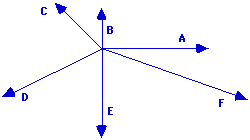
46. Express the direction of each of the following vectors in the diagram below.
|
A: 0 deg
|
B: 90 deg
|
C: 135 deg
|
D: 205 deg
|
E: 270 deg
|
F: 340 deg
|
Answer: See answers above.
The convention that the direction of a vector is measured as the counterclockwise angle of rotation of that vector from due east is used. As such, an eastward vector (A) has a direction of 0 degrees; a northward vector (B) has a direction of 90 degrees; and a southward vector (E) has a direction of 270 degrees. A protractor must be used to determine the directions of C, D and F. Vector C is in the second quadrant, so its direction is between 90 degrees and 180 degrees. The angle between East and vector C can be measured. Vector D is in the third quadrant; its direction is between 180 degrees and 270 degrees. A protractor can be used to measure the angle between West (180 degrees) and vector D. This angle measure can be added to 180 degrees to get the answer. A similar procedure is repeated with Vector F.
[ #46 | #47 | #48 | #49 | #50 | #51 | #52 | #53 | #54 | #55 ]
47. In the following diagrams, two vectors are being added and the resultant is drawn. For each diagram, identify which vector is the resultant and write the equation (e.g., A + B = C).
|
a.

The resultant is vector B.
The equation is C + A = B.
|
b.

The resultant is vector B.
The equation is A + C = B.
|
|
c.

The resultant is vector A.
The equation is C + B = A.
|
d.

The resultant is vector C.
The equation is A + B = C.
|
Answer: See answers above.
Vectors are added by a head-to-tail method and the resultant is drawn from the tail of the first vector to the head of the last vector. So if two vectors are added - say B is added to A (as in A + B) - then first A is drawn and the tail of B is placed at the head of A. The resultant is drawn with its tail at the tail of A and its head at the head of B. Thus, when the tails of two vectors are seen connected, one of the vectors is the resultant and the other is the first vector being added. And when the heads of two vectors are seen connected, one of the vectors is the resultant and the other is the second vector being added. These principles can be applied to answer the above questions.
[ #46 | #47 | #48 | #49 | #50 | #51 | #52 | #53 | #54 | #55 ]
48. Consider the five vectors shown below; they are labeled A, B, C, D and E.
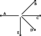
Use the stated magnitude and direction of these vectors to sketch a vector addition diagram for the following vector operations and determine the resultant. You only need to construct an approximate sketch; there is no need to do a scaled diagram.
|
A + B + C

|
A + C + B

|
A + E + D

|
|
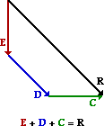
E + D + C
|
C - D

|
B + E - C

|
Answer: See diagrams above.
Vectors are added using a head-to-tail method. The magnitude and direction of the vectors are maintained when the addition (and subtraction) operations are performed. In your sketched diagrams, you should be sure to:
- place the tail of the second vector in the equation at the head of the first vector in the equation
- label each vector (A, B, C ...)
- draw the resultant from the tail of the first vector to the head of the last vector
- label the resultant
A subtraction operation is the same as adding the negative of a vector. So if D is to be subtracted from C, then simply add a vector whose magnitude is the same as D but is directed in the opposite direction.
[ #46 | #47 | #48 | #49 | #50 | #51 | #52 | #53 | #54 | #55 ]
49. A hiker's motion can be described by the following three displacement vectors.
22.0 km, 45 degrees + 16.0 km, 135 degrees + 12.0 km, 270 degrees
Add the three displacement vectors using the head-to-tail method of vector addition. Then answer the following two questions.
(a) What is the distance walked by the hiker?
(b) What is the resulting displacement of the hiker?
Answer: Distance = 50.0 km; Displacement = 15.5 km, 74 degrees
Distance is a scalar quantity and does not regard the direction of the individual legs of the hike as being important. So the distance is simply the arithmetic sum of the distances of the three individual legs of the hike. Distance = 22.0 km + 16.0 km + 12.0 km = 50.0 km
Displacement is a vector quantity which is equal to the vector sum of the individual displacements of the three-legged hike. A scaled vector addition diagram serves as a useful tool in determining this sum. A convenient scale (such as 1 cm = 4 km or 1 cm = 5 km or 1 cm = 8 km) is chosen and the vectors are added using the head-to-tail method. This is shown in the diagram below.
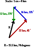
Once the resultant is drawn, the magnitude (in cm) can be measured and the scale can be used to convert to kilometers. The direction can be measured from the diagram as the counterclockwise angle of rotation from due East. The displacement is 15.5 km at 74 degrees.
[ #46 | #47 | #48 | #49 | #50 | #51 | #52 | #53 | #54 | #55 ]
50. Solve the following problem using a vector addition diagram.
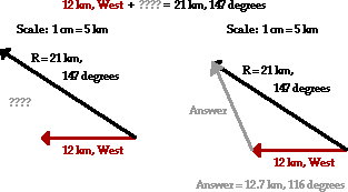
A hiker hikes for 12.0 km, west. She then makes a turn and hikes in a straight line until she reaches her final destination. If the resultant displacement is 21.0 km at 147 degrees, then what was the displacement (magnitude and direction) of the second leg of the hike?
Answer: 12.7 km, 116 degrees
This is a unique problem in that the resultant is given and one of the two vectors is given. The problem requests the magnitude and direction of the second vector. In the diagram below, the first vector is drawn and the resultant is drawn beginning at the tail of the first vector. The second vector would stretch from the head of the first vector to the head of the resultant. This can be drawn in the diagram and its magnitude and direction can be determined.
 [ #46 | #47 | #48 | #49 | #50 | #51 | #52 | #53 | #54 | #55 ]
51. Consider the trajectory diagram shown below for a horizontally launched projectile. On the diagram, draw vector arrows representing the vx and vy velocity components during the course of the motion. The length of the arrows should represent the magnitude of the velocity components. Label each component. (Note that the velocity components are already shown for the first position.)
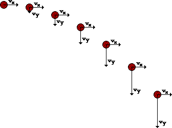
Answer: See diagram above.
A projectile has a downward acceleration. There is no horizontal acceleration; rather, the horizontal velocity remains constant. Thus, the vx vector is of constant length (i.e., magnitude) throughout the trajectory. The downward acceleration means that the vy vector will be changing. As the object falls, it speeds up. Thus, the vy vector increases its length (i.e., magnitude) throughout the trajectory. This is shown in the diagram above.
[ #46 | #47 | #48 | #49 | #50 | #51 | #52 | #53 | #54 | #55 ]
52. Consider the trajectory diagram shown below for a non-horizontally launched projectile. On the diagram, draw vector arrows representing the vx and vy velocity components during the course of the motion. The length of the arrows should represent the magnitude of the velocity components. Label each component. (Note that the velocity components are already shown for the first position.)
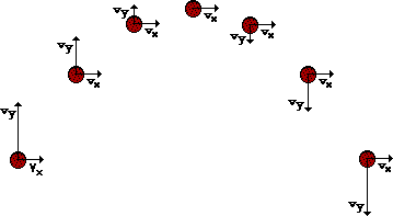
Answer: See diagram above.
A projectile has a constant horizontal velocity and a changing vertical velocity. The changing vertical component of velocity is consistent with the fact that there is a vertical acceleration. As the projectile rises towards the peak of its trajectory, the vertical velocity decreases until it reaches 0 m/s at the very peak of the trajectory. As the projectile rises towards the peak of its trajectory, the vertical velocity increases. The vertical velocity upon falling is of the same magnitude and the opposite direction as any corresponding location of the same height during the rising motion. The horizontal velocity remains constant throughout the trajectory. These principles are shown in the diagram above.
[ #46 | #47 | #48 | #49 | #50 | #51 | #52 | #53 | #54 | #55 ]
53. Consider the diagram below. The blue path represents the trajectory of a projectile dropped from rest from the top of the path. (Each ball location represents the location after a 1-second interval of time.) The red path represents the trajectory of the same ball thrown horizontally in the absence of gravity. Construct a third path accurately showing the trajectory of a projectile launched with the same horizontal speed as the red ball. Show the location during the first four seconds of motion. Finally, the (x, y) coordinate position of location 1 is (0 m, -5 m) and the (x, y) coordinate position of location 2 is (15 m, 0 m). Determine the (x, y) coordinate positions of the four locations in your trajectory. (Assume g ~10 m/s/s.)
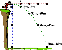
Answer: See diagram above.
A projectile such as this has both a horizontal and vertical component of motion. These two components of motion are independent of each other. The strictly vertical motion of the ball (the blue path above) depicts the vertical displacement at 1-second intervals. If a horizontal motion is imparted to the ball, its vertical displacement will not be effected since these two components are independent of each other. The strictly horizontal motion of the ball (the red path above) portrays the motion of the ball in the absence of gravity. The presence of gravity would cause the ball to accelerate downward. This vertical motion does not effect the horizontal motion since these two components are independent of each other. The green path represents the motion of the projectile when gravity acts upon it and a horizontal motion is imparted to it. The horizontal location at each 1-second instant in time is the same position as it was in the red path above it. And the vertical location at each 1-second instant in time is the same position as it was in the blue path to the left of it.
The actual coordinate positions can be determined using the kinematic equations and the given time. For the x-coordinate, the displacement is the same each second - that is, there is a constant horizontal velocity. Since location 2 has a x-coordinate of 15 m, each consecutive location will be 15 m further than the one before it. The y-coordinate is determined by using the 0.5•a•t2 expression with times of 1 s, 2 s, 3 s, and 4 s. The simplification that g is ~10 m/s2 is used to simplify the math and highlight the concept.
[ #46 | #47 | #48 | #49 | #50 | #51 | #52 | #53 | #54 | #55 ]
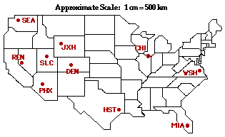
54. Consider the map of the United States at the right. Given the scale that 1 cm = 500 km, use a protractor and a ruler to determine the displacement of a traveler for the listed trips. A couple trips include two "legs." Indicate both the magnitude and the direction (using the counterclockwise from East convention) for the resultant displacement vector of the traveler.
|
Trip
|
Magnitude
|
Direction
|
|
a. From Chicago (CHI) to Washington, DC (WSH)
|
|
|
|
b. From Chicago (CHI) to Seattle (SEA)
|
|
|
|
c. From Jackson Hole (JXH) to Houston (HST)
|
|
|
|
d. From Denver (DEN) to Phoenix (PHX) to Washington (WSH)
|
|
|
|
e. From Salt Lake City (SLC) to Reno (REN) to Miami (MIA)
|
|
|
Answer: See table above.
a. The distance from CHI to WSH is ~2.6 cm. According to scale, this would be equivalent to ~1300 km. The direction of this displacement vector is measured as the counterclockwise angle of rotation from due East - 341 degrees.
b. The distance from CHI to SEA is ~6.7 cm. According to scale, this would be equivalent to ~3400 km. The direction of this displacement vector is measured as the counterclockwise angle of rotation from due East - 165 degrees.
c. The distance from JHX to HST is ~4.3 cm. According to scale, this would be equivalent to ~220 km. The direction of this displacement vector is measured as the counterclockwise angle of rotation from due East - 312 degrees.
d. This is a two-legged trip. Yet the displacement only depends upon the initial and final locations. When the traveler is done with the trip, he/she is displaced by an amount equal to the distance from DEN to WSH. This is ~6.4 cm on the map. According to scale, this would be equivalent to ~3200 km. The direction of this displacement vector is measured as the counterclockwise angle of rotation from due East - 356 degrees.
e. Again, the displacement only depends upon the initial and final locations. When the traveler is done with the trip, he/she is displaced by an amount equal to the distance from SLC to MIA. This is ~7.7 cm on the map. According to scale, this would be equivalent to ~3900 km. The direction of this displacement vector is measured as the counterclockwise angle of rotation from due East - 334 degrees.
[ #46 | #47 | #48 | #49 | #50 | #51 | #52 | #53 | #54 | #55 ]
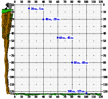
55. A cannonball is launched from the top of a 125-meter high cliff with an initial horizontal speed of 20 m/s. The (x, y) coordinate position of the launch location is designated as the (0, 0) position. Determine the (x, y) coordinate positions of the cannonball at 1-second intervals during its path to the ground. Assume g = ~10 m/s/s, down.
Answer: See diagram above.
The horizontal speed is 20 m/s throughout the trajectory. So the projectile will move a distance of 20 meters in each second. This horizontal displacement is combined with a falling motion which drops the projectile some vertical distance below the initial height of the cannon. The vertical displacement is given by the 0.5•a•t2 expression where the a value is stated as ~10 m/s2. Times of 1 s, 2 s, 3 s, etc. can be substituted into this expression to determine the vertical displacements of -5 m, -20 m, -45 m, -80 m, -125 m.
[ #46 | #47 | #48 | #49 | #50 | #51 | #52 | #53 | #54 | #55 ]
Navigate to:
Review Session Home - Topic Listing
Vectors and Projectiles - Home ||
Printable Version ||
Questions and Links
Answers to Questions:
All ||
#1-9 ||
#10-45 ||
#46-55 ||
#56-72
You Might Also Like ...
Users of The Review Session are often looking for learning resources that provide them with practice and review opportunities that include built-in feedback and instruction. If that is what you're looking for, then you might also like the following:
- The Calculator Pad
The Calculator Pad includes physics word problems organized by topic. Each problem is accompanied by a pop-up answer and an audio file that explains the details of how to approach and solve the problem. It's a perfect resource for those wishing to improve their problem-solving skills.
Visit: The Calculator Pad Home | Calculator Pad - Vectors and Projectiles
- Minds On Physics the App Series
Minds On Physics the App ("MOP the App") is a series of interactive questioning modules for the student that is serious about improving their conceptual understanding of physics. Each module of the series covers a different topic and is further broken down into sub-topics. A "MOP experience" will provide a learner with challenging questions, feedback, and question-specific help in the context of a game-like environment. It is available for phones, tablets, Chromebooks, and Macintosh computers. It's a perfect resource for those wishing to refine their conceptual reasoning abilities. Part 1 of the series includes Vectors and Projectiles.
Visit: MOP the App Home || MOP the App - Part 1