Hold down the T key for 3 seconds to activate the audio accessibility mode, at which point you can click the K key to pause and resume audio. Useful for the Check Your Understanding and See Answers.
 In the first section of Lesson 4, we learned that light is reflected by convex mirrors in a manner that a virtual image is formed. We also learned that there are two simple rules of reflection for convex mirrors. These rules represent slight revisions of the two rules given for concave mirrors. The revised rules can be stated as follows:
- Any incident ray traveling parallel to the principal axis on the way to a convex mirror will reflect in such a manner that its extension will pass through the focal point.
- Any incident ray traveling towards a convex mirror such that its extension passes through the focal point will reflect and travel parallel to the principal axis.
These two rules will be used to construct ray diagrams. A ray diagram is a tool that is used to determine the location, size, orientation, and type of image formed by a mirror. Ray diagrams for concave mirrors were drawn in Lesson 3. In this lesson, we will see a similar method for constructing ray diagrams for convex mirrors.
Step-by-Step Procedure for Drawing Ray Diagrams
The method of drawing ray diagrams for convex mirrors is described below.
 1. Pick a point on the top of the object and draw two incident rays traveling towards the mirror.
Using a straight edge, accurately draw one ray so that it travels towards the focal point on the opposite side of the mirror; this ray will strike the mirror before reaching the focal point; stop the ray at the point of incidence with the mirror. Draw the second ray such that it travels exactly parallel to the principal axis. Place arrowheads upon the rays to indicate their direction of travel.
 2. Once these incident rays strike the mirror, reflect them according to the two rules of reflection for convex mirrors.
The ray that travels towards the focal point will reflect and travel parallel to the principal axis. Use a straight edge to accurately draw its path. The ray that traveled parallel to the principal axis on the way to the mirror will reflect and travel in a direction such that its extension passes through the focal point. Align a straight edge with the point of incidence and the focal point, and draw the second reflected ray. Place arrowheads upon the rays to indicate their direction of travel. The two rays should be diverging upon reflection.
 3. Locate and mark the image of the top of the object.
The image point of the top of the object is the point where the two reflected rays intersect. Since the two reflected rays are diverging, they must be extended behind the mirror in order to intersect. Using a straight edge, extend each of the rays using dashed lines. Draw the extensions until they intersect. The point of intersection is the image point of the top of the object. Both reflected rays would appear to diverge from this point. If your were to draw a third pair of incident and reflected rays, then the extensions of the third reflected ray would also pass through this point. This is merely the point where all light from the top of the object would appear to diverge from upon reflecting off the mirror. Of course, the rest of the object has an image as well and it can be found by applying the same three steps for another chosen point. See note below.
 4. Repeat the process for the bottom of the object.
The goal of a ray diagram is to determine the location, size, orientation, and type of image that is formed by the convex mirror. Typically, this requires determining where the image of the upper and lower extreme of the object is located and then tracing the entire image. After completing the first three steps, only the image location of the top extreme of the object has been found. Thus, the process must be repeated for the point on the bottom of the object. If the bottom of the object lies upon the principal axis (as it does in this example), then the image of this point will also lie upon the principal axis and be the same distance from the mirror as the image of the top of the object. At this point the complete image can be filled in.
Some students have difficulty understanding how the entire image of an object can be deduced once a single point on the image has been determined. If the object is merely a vertical object (such as the arrow object used in the example below), then the process is easy. The image is merely a vertical line. This is illustrated in the diagram below. In theory, it would be necessary to pick each point on the object and draw a separate ray diagram to determine the location of the image of that point. That would require a lot of ray diagrams as illustrated in the diagram below.
Fortunately, a shortcut exists. If the object is a vertical line, then the image is also a vertical line. For our purposes, we will only deal with the simpler situations in which the object is a vertical line that has its bottom located upon the principal axis. For such simplified situations, the image is a vertical line with the lower extremity located upon the principal axis.
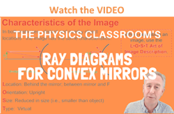
The ray diagram above illustrates that the image of an object in front of a convex mirror will be located at a position behind the convex mirror. Furthermore, the image will be upright, reduced in size (smaller than the object), and virtual. This is the type of information that we wish to obtain from a ray diagram. The characteristics of this image will be discussed in more detail in the next section of Lesson 4.
Once the method of drawing ray diagrams is practiced a couple of times, it becomes as natural as breathing. Each diagram yields specific information about the image. It is suggested that you take a few moments to practice a few ray diagrams on your own and to describe the characteristics of the resulting image. The diagrams below provide the setup; you must merely draw the rays and identify the image. If necessary, refer to the method described above.

We Would Like to Suggest ...

Why just read about it and when you could be interacting with it? Interact - that's exactly what you do when you use one of The Physics Classroom's Interactives. We would like to suggest that you combine the reading of this page with the use of our
Optics Bench Interactive or our
Name That Image Interactive. You can find this in the Physics Interactives section of our website. The
Optics Bench Interactive provides the learner an interactive enivronment for exploring the formation of images by lenses and mirrors. The
Name That Image Interactive provides learners with an intensive mental workout in recognizing the image characteristics for any given object location in front of a curved mirror.