Hold down the T key for 3 seconds to activate the audio accessibility mode, at which point you can click the K key to pause and resume audio. Useful for the Check Your Understanding and See Answers.
 One theme of the Reflection and Refraction units of The Physics Classroom Tutorial has been that we see an object because light from the object travels to our eyes as we sight along a line at the object. Similarly, we see an image of an object because light from the object reflects off a mirror or refracts through a transparent material and travel to our eyes as we sight at the image location of the object. From these two basic premises, we have defined the image location as the location in space where light appears to diverge from. Because light emanating from the object converges or appears to diverge from this location, a replica or likeness of the object is created at this location. For both reflection and refraction scenarios, ray diagrams have been a valuable tool for determining the path of light from the object to our eyes.
Applying the Three Rules of Refraction
In this section of Lesson 5, we will investigate the method for drawing ray diagrams for objects placed at various locations in front of a double convex lens. To draw these ray diagrams, we will have to recall the three rules of refraction for a double convex lens:
- Any incident ray traveling parallel to the principal axis of a converging lens will refract through the lens and travel through the focal point on the opposite side of the lens.
- Any incident ray traveling through the focal point on the way to the lens will refract through the lens and travel parallel to the principal axis.
- An incident ray that passes through the center of the lens will in effect continue in the same direction that it had when it entered the lens.
Earlier in this lesson, the following diagram illustrating the path of light from an object through a lens to an eye placed at various locations was shown.
In this diagram, five incident rays are drawn along with their corresponding refracted rays. Each ray intersects at the image location and then travels to the eye of an observer. Every observer would observe the same image location and every light ray would follow the Snell's Law of refraction. Yet only two of these rays would be needed to determine the image location since it only requires two rays to find the intersection point. Of the five incident rays drawn, three of them correspond to the incident rays described by our three rules of refraction for converging lenses. We will use these three rays through the remainder of this lesson, merely because they are the easiest rays to draw. Certainly two rays would be all that is necessary; yet the third ray will provide a check of the accuracy of our process.
Step-by-Step Method for Drawing Ray Diagrams
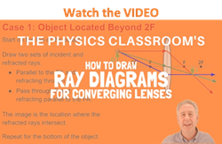
The method of drawing ray diagrams for double convex lens is described below. The description is applied to the task of drawing a ray diagram for an object located beyond the 2F point of a double convex lens.
 1. Pick a point on the top of the object and draw three incident rays traveling towards the lens.
Using a straight edge, accurately draw one ray so that it passes exactly through the focal point on the way to the lens. Draw the second ray such that it travels exactly parallel to the principal axis. Draw the third incident ray such that it travels directly to the exact center of the lens. Place arrowheads upon the rays to indicate their direction of travel.
 2. Once these incident rays strike the lens, refract them according to the three rules of refraction for converging lenses.
The ray that passes through the focal point on the way to the lens will refract and travel parallel to the principal axis. Use a straight edge to accurately draw its path. The ray that traveled parallel to the principal axis on the way to the lens will refract and travel through the focal point. And the ray that traveled to the exact center of the lens will continue in the same direction. Place arrowheads upon the rays to indicate their direction of travel. Extend the rays past their point of intersection.
 3. Mark the image of the top of the object.
The image point of the top of the object is the point where the three refracted rays intersect. All three rays should intersect at exactly the same point. This point is merely the point where all light from the top of the object would intersect upon refracting through the lens. Of course, the rest of the object has an image as well and it can be found by applying the same three steps to another chosen point. (See note below.)
 4. Repeat the process for the bottom of the object.
One goal of a ray diagram is to determine the location, size, orientation, and type of image that is formed by the double convex lens. Typically, this requires determining where the image of the upper and lower extreme of the object is located and then tracing the entire image. After completing the first three steps, only the image location of the top extreme of the object has been found. Thus, the process must be repeated for the point on the bottom of the object. If the bottom of the object lies upon the principal axis (as it does in this example), then the image of this point will also lie upon the principal axis and be the same distance from the mirror as the image of the top of the object. At this point the entire image can be filled in.
Some students have difficulty understanding how the entire image of an object can be deduced once a single point on the image has been determined. If the object is merely a vertical object (such as the arrow object used in the example below), then the process is easy. The image is merely a vertical line. In theory, it would be necessary to pick each point on the object and draw a separate ray diagram to determine the location of the image of that point. That would require a lot of ray diagrams as illustrated in the diagram below.
Fortunately, a shortcut exists. If the object is a vertical line, then the image is also a vertical line. For our purposes, we will only deal with the simpler situations in which the object is a vertical line that has its bottom located upon the principal axis. For such simplified situations, the image is a vertical line with the lower extremity located upon the principal axis.
The ray diagram above illustrates that when the object is located at a position beyond the 2F point, the image will be located at a position between the 2F point and the focal point on the opposite side of the lens. Furthermore, the image will be inverted, reduced in size (smaller than the object), and real. This is the type of information that we wish to obtain from a ray diagram. These characteristics of the image will be discussed in more detail in the next section of Lesson 5.
Once the method of drawing ray diagrams is practiced a couple of times, it becomes as natural as breathing. Each diagram yields specific information about the image. The two diagrams below show how to determine image location, size, orientation and type for situations in which the object is located at the 2F point and when the object is located between the 2F point and the focal point.
It should be noted that the process of constructing a ray diagram is the same regardless of where the object is located. While the result of the ray diagram (image location, size, orientation, and type) is different, the same three rays are always drawn. The three rules of refraction are applied in order to determine the location where all refracted rays appear to diverge from (which for real images, is also the location where the refracted rays intersect).
Ray Diagram for Object Located in Front of the Focal Point
In the three cases described above - the case of the object being located beyond 2F, the case of the object being located at 2F, and the case of the object being located between 2F and F - light rays are converging to a point after refracting through the lens. In such cases, a real image is formed. As discussed previously, a real image is formed whenever refracted light passes through the image location. While diverging lenses always produce virtual images, converging lenses are capable of producing both real and virtual images. As shown above, real images are produced when the object is located a distance greater than one focal length from the lens. A virtual image is formed if the object is located less than one focal length from the converging lens. To see why this is so, a ray diagram can be used.
 A ray diagram for the case in which the object is located in front of the focal point is shown in the diagram at the right. Observe that in this case the light rays diverge after refracting through the lens. When refracted rays diverge, a virtual image is formed. The image location can be found by tracing all light rays backwards until they intersect. For every observer, the refracted rays would seem to be diverging from this point; thus, the point of intersection of the extended refracted rays is the image point. Since light does not actually pass through this point, the image is referred to as a virtual image. Observe that when the object in located in front of the focal point of the converging lens, its image is an upright and enlarged image that is located on the object's side of the lens. In fact, one generalization that can be made about all virtual images produced by lenses (both converging and diverging) is that they are always upright and always located on the object's side of the lens.
Ray Diagram for Object Located at the Focal Point
Thus far we have seen via ray diagrams that a real image is produced when an object is located more than one focal length from a converging lens; and a virtual image is formed when an object is located less than one focal length from a converging lens (i.e., in front of F). But what happens when the object is located at F? That is, what type of image is formed when the object is located exactly one focal length from a converging lens? Of course a ray diagram is always one tool to help find the answer to such a question. However, when a ray diagram is used for this case, an immediate difficulty is encountered. The diagram below shows two incident rays and their corresponding refracted rays.
For the case of the object located at the focal point (F), the light rays neither converge nor diverge after refracting through the lens. As shown in the diagram above, the refracted rays are traveling parallel to each other. Subsequently, the light rays will not converge to form a real image; nor can they be extended backwards on the opposite side of the lens to intersect to form a virtual image. So how should the results of the ray diagram be interpreted? The answer: there is no image!! Surprisingly, when the object is located at the focal point, there is no location in space at which an observer can sight from which all the refracted rays appear to be coming. An image cannot be found when the object is located at the focal point of a converging lens.
We Would Like to Suggest ...

Why just read about it and when you could be interacting with it? Interact - that's exactly what you do when you use one of The Physics Classroom's Interactives. We would like to suggest that you combine the reading of this page with the use of our
Optics Bench Interactive. You can find this in the Physics Interactives section of our website. The
Optics Bench Interactive provides the learner an interactive enivronment for exploring the formation of images by lenses and mirrors. Its like having a complete optics toolkit on your screen.