Chapter 19: Reflection and Mirrors - Lesson 2: Image Formation in Plane Mirrors
Other Multiple Mirror Systems
Hold down the T key for 3 seconds to activate the audio accessibility mode, at which point you can click the K key to pause and resume audio. Useful for the Check Your Understanding and See Answers.
Besides right angle mirror systems, there is a wealth of other multiple mirror systems that involve two or more mirrors. If two plane mirrors are placed together on one of their edges so as to form a right angle mirror system and then the angle between them is decreased, some interesting observations can be made. One observes that as the angle between the mirrors decreases, the number of images that can be seen increases. In fact as the angle between the mirrors approaches 0 degrees (i.e., the mirrors are parallel to each other), the number of images approaches infinity.
 Determining Image Locations for Multiple Mirror Systems
The generation of two images is not difficult to explain; each of the two mirrors produces an image due to the single reflection of light off one of the mirror faces to an observer's eye. The remaining images are produced as the result of multiple reflections of light off more than one of the faces. Right angle mirrors will allow a maximum of two reflections of light from the object. But as the angle decreases, three, four, and even more reflections can occur.
Determining the image locations for such multiple mirror systems can become complicated. First determine the location of the primary images using the principle that the image distance to the mirror is the same as the object distance to the mirror. Each primary image forms a secondary image as a result of a double reflection. By extending one of the mirror lines, a primary image can be reflected (a geometry term, not a physics term) across the second mirror line to form a secondary image - an image of an image. As an example, consider the diagram below for an object placed between two plane mirrors that make a 60-degree angle. Images I1 and I2 are primary images formed by the two plane mirrors. Image I3 was found by reflecting image I2 across the extension of the top mirror. And image I4 was found by reflecting the image I1 across the side mirror. The process can be repeated to determine the location of an image of an image of an image.
Ray diagrams for these multiple mirror systems are drawn much like they were for right angle mirror systems. Once you have located the images, begin by drawing a line of sight towards the image; this would be the reflected ray that ultimately travels to your eye. For a secondary image, this reflected ray is associated with an incident ray that had reflected off the other face of the mirror. The law of reflection can be used to determine the direction it was traveling as it was incident upon this face of the mirror. Repeat this process to determine the point of reflections on each face, tracing the path of light back to its origin - the object itself. A completed ray diagram for a secondary image on a 60-degree mirror system is shown below.
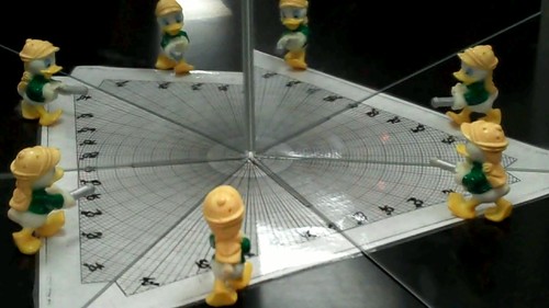
Flickr Physics Photo
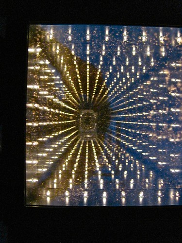
A Pair of Parallel Mirrors
When the two mirrors are aligned at a 0-degree angle with each other (i.e., a parallel mirror system), there is an infinite number of images. Each image is the result of an image of an image, or an image of an image of an image or an image of an image of ... . The diagram below shows the multiple images for a parallel mirror system. Images I1 and I2 are primary images. Image I1 is the image resulting from the reflection of the object O across mirror M1 and image I2 is the image resulting from the reflection of the object O across mirror M2. Image I3 is an image of image I1, found by reflecting image I1 across mirror M2. Image I4 is an image of image I2; found by reflecting image I2 across mirror M1. This process could continue indefinitely, producing images of images for an infinite number of images extending to the right of mirror M2 and to the left of mirror M1.

Multiple mirror systems are merely the extension of what we have already learned about plane mirrors. The locating of images is an extension of the principle that the image distance to the mirror is the same as the object distance to the mirror. Drawing ray diagrams for multiple mirror systems is an extension of the line of sight and law of reflection principles.
Flickr Physics Photo
1. Rose Inhatt stands between a set of parallel plane mirrors (M1 and M2) as shown in the diagram below. There is a flower on Rose's hat that is located a distance of 0.4 m from M1 and a distance of 1.0 m from M2. Since the mirrors are parallel, Rose will see an infinite number of images of the flower as she looks in mirror M2. These images stretch towards infinity. Some of the images are closer to the mirror than others.

Determine the distance between mirror M2 and the...
a. ... nearest image ____________
b. ... second nearest image____________
c. ... the third nearest image ____________
See Answer