Hold down the T key for 3 seconds to activate the audio accessibility mode, at which point you can click the K key to pause and resume audio. Useful for the Check Your Understanding and See Answers.
 The line of sight principle suggests that in order to view an image of an object in a mirror, a person must sight along a line at the image of the object. When sighting along such a line, light from the object reflects off the mirror according to the law of reflection and travels to the person's eye. This process was discussed and explained earlier in this lesson. One useful tool that is frequently used to depict this idea is known as a ray diagram. A ray diagram is a diagram that traces the path that light takes in order for a person to view a point on the image of an object. On the diagram, rays (lines with arrows) are drawn for the incident ray and the reflected ray. Complex objects such as people are often represented by stick figures or arrows. In such cases it is customary to draw rays for the extreme positions of such objects.
 Drawing Ray Diagrams - a Step-by-Step Approach
This section of Lesson 2 details and illustrates the procedure for drawing ray diagrams. Let's begin with the task of drawing a ray diagram to show how Suzie will be able to see the image of the green object arrow in the diagram below. For simplicity sake, we will suppose that Suzie is viewing the image with her left eye closed. Thus, we will focus on how light travels from the two extremities of the object arrow (the left and right side) to the mirror and finally to Suzie's right eye as she sights at the image. The four steps of the process for drawing a ray diagram are listed, described and illustrated below.
1. Draw the image of the object.
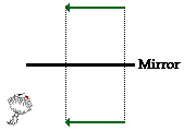 Use the principle that the object distance is equal to the image distance to determine the exact location of the object. Pick one extreme on the object and carefully measure the distance from this extreme point to the mirror. Mark off the same distance on the opposite side of the mirror and mark the image of this extreme point. Repeat this process for all extremes on the object until you have determined the complete location and shape of the image. Note that all distance measurements should be made by measuring along a segment that is perpendicular to the mirror.
2. Pick one extreme on the image of the object and draw the reflected ray that will travel to the eye as it sights at this point.
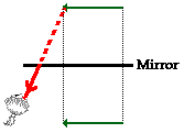 Use the line of sight principle: the eye must sight along a line at the image of the object in order to see the image of the object. It is customary to draw a bold line for the reflected ray (from the mirror to the eye) and a dashed line as an extension of this reflected ray; the dashed line extends behind the mirror to the location of the image point. The reflected ray should have an arrowhead upon it to indicate the direction that the light is traveling. The arrowhead should be pointing towards the eye since the light is traveling from the mirror to the eye, thus enabling the eye to see the image.
3. Draw the incident ray for light traveling from the corresponding extreme on the object to the mirror.
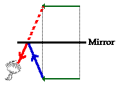 The incident ray reflects at the mirror's surface according to the law of reflection. But rather than measuring angles, you can merely draw the incident ray from the extreme of the object to the point of incidence on the mirror's surface. Since you drew the reflected ray in step 2, the point of incidence has already been determined; the point of incidence is merely the point where the line of sight intersects the mirror's surface. Thus draw the incident ray from the extreme point to the point of incidence. Once more, be sure to draw an arrowhead upon the ray to indicate its direction of travel. The arrowhead should be pointing towards the mirror since light travels from the object to the mirror.
4. Repeat steps 2 and 3 for all other extremities on the object.
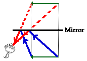 After completing steps 2 and 3, you have only shown how light travels from a single extreme on the object to the mirror and finally to the eye. You will also have to show how light travels from the other extremes on the object to the eye. This is merely a matter of repeating steps 2 and 3 for each individual extreme. Once repeated for each extreme, your ray diagram is complete.
Your Turn to Practice
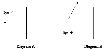
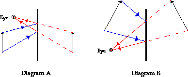
The best way to learn to draw ray diagrams involves trying it yourself. It's easy. Merely duplicate the two setups below onto a blank sheet of paper, grab a ruler/straightedge, and begin. If necessary, refer to the four-step procedure listed above. When finished, compare your diagram with the completed diagrams at the bottom of this page.
Uses of Ray Diagrams
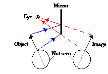 Ray diagrams can be particularly useful for determining and explaining why only a portion of the image of an object can be seen from a given location. The ray diagram at the right shows the lines of sight used by the eye in order to see a portion of the image in the mirror. Since the mirror is not long enough, the eye can only view the topmost portion of the image. The lowest point on the image that the eye can see is that point in line with the line of sight that intersects the very bottom of the mirror. As the eye tries to view even lower points on the image, there is not sufficient mirror present to reflect light from the lower points on the object to the eye. The portion of the object that cannot be seen in the mirror is shaded green in the diagram below.
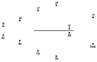
Similarly, ray diagrams are useful tools for determining and explaining what objects might be viewed when sighting into a mirror from a given location. For example, suppose that six students - Al, Bo, Cy, Di, Ed, and Fred sit in front of a plane mirror and attempt to see each other in the mirror. And suppose the exercise involves answering the following questions: Whom can Al see? Whom can Bo see? Whom can Cy see? Whom can Di see? Whom can Ed see? And whom can Fred see?

The task begins by locating the images of the given students. Then, Al is isolated from the rest of the students and lines of sight are drawn to see who Al can see. The leftward-most student whom Al can see is the student whose image is to the right of the line of sight that intersects the left edge of the mirror. This would be Ed. The rightward-most student who Al can see is the student whose image is to the left of the line of sight that intersects the right edge of the mirror. This would be Fred. Al could see any student positioned between Ed and Fred by looking at any other positions along the mirror. However in this case, there are no other students between Ed and Fred; thus, Ed and Fred are the only students whom Al can see? The diagram below illustrates this using lines of sight for Al.
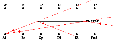
 Of course the same process can be repeated for the other students by observing their lines of sight. Perhaps you will want to try to determine whom Bo, Cy, Di, Ed, and Fred can see? Then check your answers by clicking the button below.
Check Your Understanding
1. Six students are arranged in front of a mirror. Their positions are shown below. The image of each student is also drawn on the diagram. Make the appropriate line of sight constructions to determine that students each individual student can see.

Here are completed diagrams for the two examples given above in the Your Turn to Practice section.
Back to Diagram.