Chapter 9: Rotation and Balance - Lesson 2: Rotational Dynamics
Torque
Hold down the T key for 3 seconds to activate the audio accessibility mode, at which point you can click the K key to pause and resume audio. Useful for the Check Your Understanding and See Answers.
Understanding Torque
Imagine a top view of a door that is hinged on the right end. You need to open the door, but no handle is attached. At which location would your pushing force be most effective in causing the door to rotate?
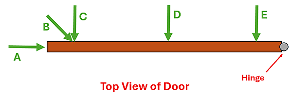
If you said, location "C", you are right. But why? If you apply the same force to the same object, shouldn't you get the same results? Actually not. Whereas pushing an isolated object with a force from any direction will cause the same size linear acceleration, for a hinged object that will rotate, where you apply the force determines its effectiveness to produce rotation. That brings us to the first big idea for this lesson—the concept of torque.
Torque: The effectiveness of a force to produce rotation
In Lesson 1, we made several comparisons between translational (linear) quantities used to describe how an object moves and their rotational counterparts. In this lesson, we'll do the same with quantities related to the why of motion.
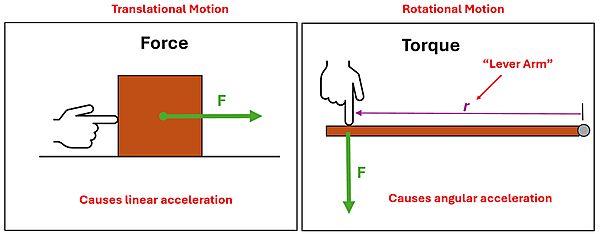
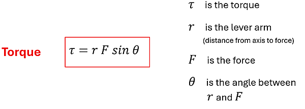
A torque on an object is what makes that object start to rotate. The amount of torque depends on three things: (1) the force applied, (2) the lever arm (the distance that the force acts from the axis of rotation), and (3) the angle between the lever arm vector and the force vector. We can calculate the torque on an object using this equation:
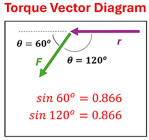
The lever arm and the force are both vector quantities because they each point in a particular direction. What physicists often do to determine θ is they draw r (in the direction from the axis to the location of the force) and then draw F (in its direction) with its tail starting at the tip of the lever arm vector. By doing so, θ can be either the angle between the two vectors or the angle that the force vector is 'bent' from the direction of the lever arm vector. Either angle? How can that be? In our example to the below, the angle between the two vectors is 120o. The angle that the force vector is 'bent' from the direction of the lever arm is 60o. But notice that sin 60o = sin 120o = 0.866. Since our equation calls for sin θ, when we wish to calculate the torque on an object, we can use either angle because we get the same result either way. The reason this works is because these two angles are supplements (they add up to 180o) of each other. And the sine of an angle and its supplement give you the same value.
The Direction of Torque
While r and F are vectors, torque is also a vector quantity. The equation above will help us calculate the magnitude of the torque, but a vector diagram (like the diagram above) will help us determine the direction of the torque. Imagine, for example, that the lever arm is the hour hand on a clock. The clock hand is allowed to pivot at one end, just like the lever arm has an axis of rotation. Now imagine that you exert a force on the non-fixed end of the hour hand. Do you see that depending on the direction of the force on the hour hand (which represents the lever arm), you can cause it to rotate counterclockwise or clockwise? The direction that the lever arm 'wants' to rotate is the direction of the torque.
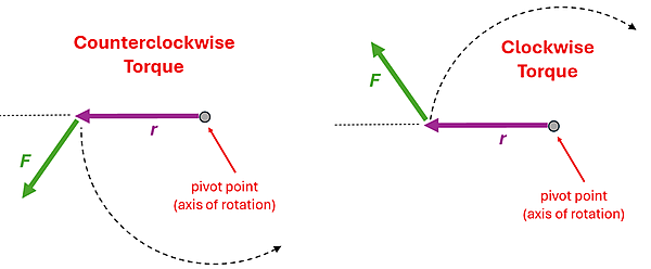
Torque will cause objects to rotate counterclockwise or clockwise. The direction of the force on the lever arm will determine the direction of the torque.
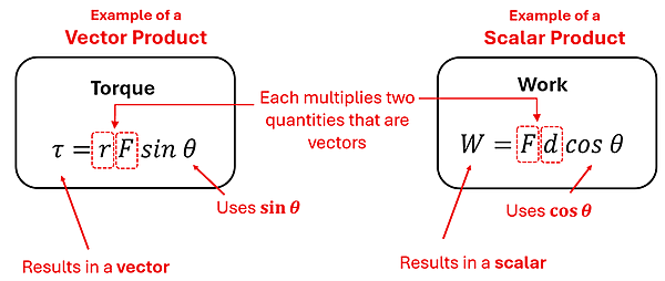
Torque is a Vector Product
Torque is an example of a vector product. A vector product, sometimes called a cross product, is a multiplication of two vector quantities (and the sine of the angle between them) where the result is also a vector. This is different from a scalar product, sometimes called a dot product, which is a multiplication of two vector quantities (and the cosine of the angle between them) resulting in a scalar quantity. Let's make a side-by-side comparison of torque (a vector) and work (a scalar) to see how these products are similar yet different.
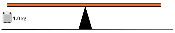
Example 1: Torque by a Hanging Mass
Problem: A meterstick is balanced at its center. A 1.0 kg mass is now attached to the left end. Determine the torque that the mass exerts on the meterstick relative to the pivot.
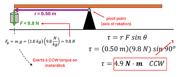
Solution: Let's begin by drawing the r and F vectors as shown below. This is important in finding both the direction of the torque as well as in determining that the angle between them is 90o. Next, to determine the force, we need to recognize that the force applied to the bar will equal the force of gravity on the mass. Since it is a 1.0 kg mass, this is conveniently 9.8 N. Finally, we'll use the torque equation to find that the torque applied to the meterstick is 4.9 N⋅m (Newton-Meter) in the CCW direction.
A word about units: While Work is a Scalar Product, and Torque is a Vector Product, both can be measured in N⋅m (Newton-Meters). Confusing, right? Just remember that when talking about Torque – It's not about energy. There is also a fair amount of variation to how Newton-Meters are represented. N⋅m, N * m, N m, N-m, Nm are all ways you may see this unit. Some teachers even use an imaginary unit m⋅N (Meter-Newtons) for torque and reserve N⋅m for work. We will be using N⋅m as it's a common and approved representation by the International System of Units (SI). If your teacher prefers another variation, then you can use that notation for the class. Overall, just know that the official unit for torque is N⋅m (Newton-Meters), and represents a Vector Product.
Example 2: Something Fishy
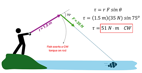
Problem : Katch DeBigwon was sure he had his prize fish on the line when he felt it pull with a force of 35 N. The end of the rod was 1.5 m from his hands. What torque was his prize fish exerting on his rod relative to his hands?
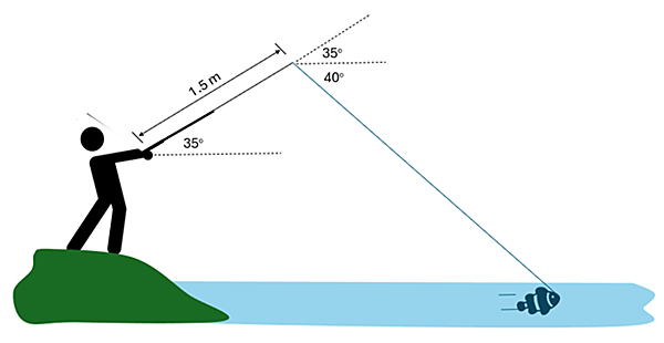
Solution : Probably the most challenging part of this problem is determining what angle to use. Remember that we can use either the angle between the lever arm vector and the force or the angle that the force vector is 'bent' from the direction of the lever arm vector. We've used the latter in this solution. We can also see that the torque exerted on the rod is in the clockwise direction. So, we'd say that the torque on the rod is 51 N·m in the CW direction.
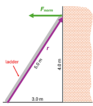
Using Perpendicular Components
Let's imagine a 5.0 m ladder resting against a building 3.0 m from the base. To hold the ladder up, the building applies a 16 N horizontal normal force. We could calculate the torque that the building applies to the ladder about the base of the ladder using the method used above. We would first need to find the angle that the ladder makes with the ground (θ = 53.1o) and then recognize that this is the same angle between the ladder and the horizontal normal force. (You might recall that alternate interior angles are congruent.) Then we would apply the torque equation and find that the torque is 64 N·m in the CCW direction.
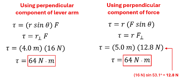
There is another way to tackle this problem, however. Let's pair the lever arm and the sine of our angle in our torque equation. Doing so, we recognize that r sin θ = r⟂, where r⟂ is the perpendicular distance from the base of the ladder to the place where the force is applied. That is the 4.0 m distance in our picture. We now just need to multiply r⟂ time F. We see that this approach gives us the same result, without even having to calculate an angle. What is just as cool is that it works the other way, too. If we pair the force and the sine of our angle, we recognize that F sin θ = F⟂, where F⟂ is the component of the force that is perpendicular to the lever arm. We see that r time F⟂ also gives the same result in calculating the torque. While all these methods work, sometimes one approach is a bit simpler depending on what is given in the problem.
Example 3: Which is More?
Problem: An "H" shaped structure is cut out of wood and suspended from a point at the top center as shown. A 5.0 N weight is hung from position A. The 5.0 N weight is then removed and hung from position B. Which location produced the greater torque relative to the pivot?

Solution: They both produce the same torque. It is true that B is further from the pivot, but the component of the lever arm that is perpendicular to the force is the same for each.
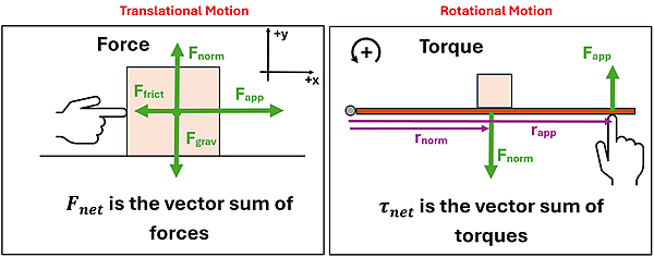
Multiple Torques at Once
Just as multiple forces can be applied to an object, multiple torques can be applied as well. To find the net force acting on an object, we found the vector sum of the forces. For example, to find the net force in the x-direction, we added the forces in the +x direction and subtracted the forces in the -x direction. To find the net torque, we'll find the vector sum of the torques. We will add the CCW torques and subtract the CW torques.
When finding the net torque, it is especially important to define our coordinate system and be consistent by calling the torque in one direction positive and the other negative. While either direction (CCW or CW) can be the positive direction, in most cases we'll choose CCW to be the positive direction so that we are consistent with our rotational kinematics coordinate system convention. We'll use the same convention as back in Lesson 1 to show that the counterclockwise direction is the direction that we are defining as the positive direction.
Example 5: Keeping Direction Straight
Problem: A meterstick is hinged at its center, and three forces are applied as shown.
(A) What is the net torque about the pivot?
(B) Which way will this system rotate?
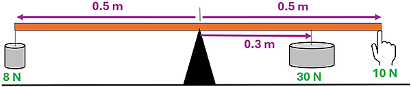
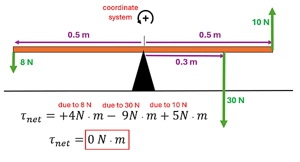
Solution: (A) Working our way from left to right, we have the 8 N weight supplying a torque of +4 N·m with respect to the pivot. Since the lever arm vector and force vector are already perpendicular, we can just multiply these two values. We call this torque positive since this force will cause the bar to rotate CCW, which is what we've defined to be the positive direction. Similarly, the 30 N weight supplies a torque of -9 N·m, and the 10 N force supplies a +5 N·m torque. Thus, the net torque is zero. (b) Since the direction of the torque is the direction the system 'wants' to rotate, this system will not rotate. We'll explore this special case (that is, when the net torque is zero) more in our next section, where we'll investigate equilibrium.
Example 6: Tipping the Scales
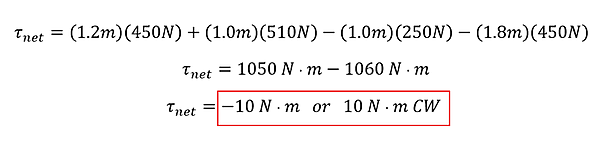
Problem: Two students sit on the left side of a playground teeter-totter. Two other students sit on the right side. The two students sitting on the left say, "We're sure the teeter-totter will tip down on our side since we weigh more."
(A) Do you agree with their claim?
(B) Support your reasoning with evidence.
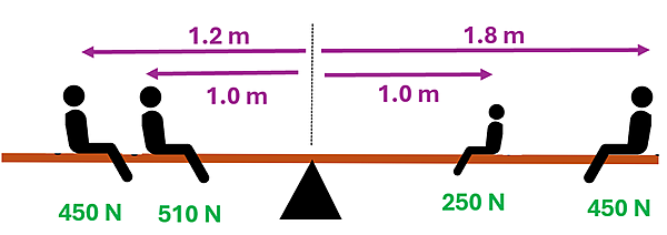
Solution: (a) No, the teeter-totter will tip in the direction of the greatest torque, not necessarily in the direction of the greatest weight. (b) It turns out that the students on the right side actually exert a greater CW torque (1060 N·m) on the tetter-totter compared to the CCW torque (1050 N·m) produced by the students on the left.
Check Your Understanding
Use the following questions to assess your understanding. Tap the Check Answer buttons when ready.
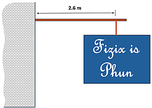
1: A 150 N sign hangs from a horizontal beam 2.6 m long that is anchored to a building. What torque does the sign exert on the bar relative to the anchor point?
2: A 45 kg bicyclist puts all her weight on the pedal each time it moves downward in order to pedal up a steep hill. The diameter of the circle in which the pedals rotate is 0.40 m. Determine the magnitude of the maximum torque she exerts relative to the axle.
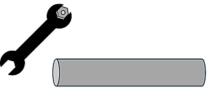
3: A mechanic needs to tighten a nut to 300 N·m of torque to meet safety requirements. The mechanic can exert a maximum force of 500 N.
(A) What minimum distance from the nut can the mechanic exert this force and accomplish the task?
(B) While the wrench is not long enough, the mechanic finds a long, hollow pipe nearby. What might the mechanic do to tighten the nut to safety specifications
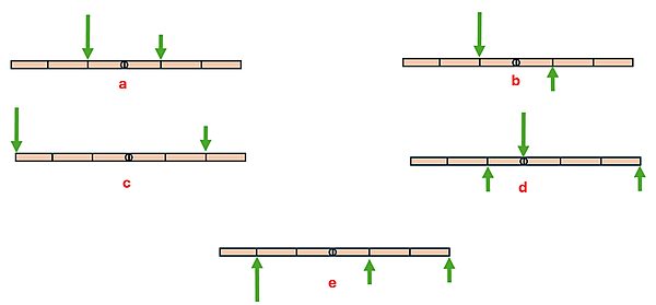
4: Five identical bars are fixed to a pivot in their center. Forces of 1 N (short arrow) or 2 N (long arrow) are applied to different locations on each bar. Rank the bars from the greatest magnitude torque (relative to the pivot) to the smallest magnitude torque.
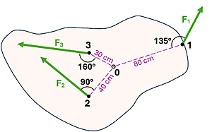
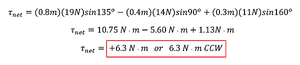
5: A piece of wood is cut into the shape shown and made to pivot about 0. Three forces (F1=19 N, F2=14 N, and F3=11 N) act on the wood in the directions shown. If CCW is the positive direction, what is the net torque on the wood relative to the pivot?
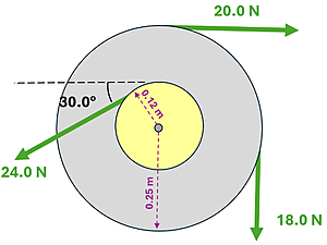
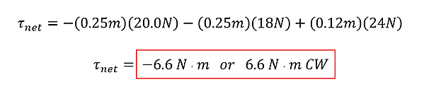
6: An inner (yellow) disk is welded to an outer (gray) metal disk. The two disks share the same axis through their centers. Cables are wrapped around the disks, and forces are applied as shown. Find the net torque on the system about the axis of rotation. Take CCW to be the positive direction.
Looking for additional practice? Check out the CalcPad for additional practice problems.