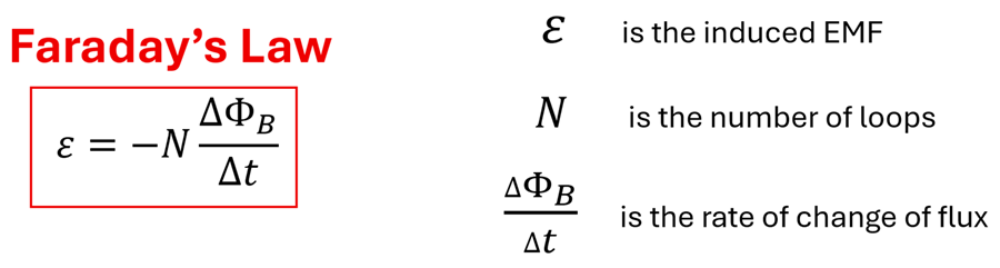
Faraday's Law
Michael Faraday is considered the father of electromagnetic induction as he observed that a change in magnetic flux through the area enclosed by a loop of wire induces a current in that loop. The animation below illustrates this phenomenon. Let’s imagine the current changes in the solenoid on the left. Since a current produces a magnetic field, a changing current will produce a changing magnetic field. This changing field, then, creates a changing magnetic flux through the single loop of wire shown to the right. As the number of B-field lines that pierce the area enclosed by this loop changes, the flux through this area changes. Faraday stated that the greater the rate of change of magnetic flux through the loop on the right, the greater the current induced in this loop. The galvanometer connected to the loop on the right illustrates that such a current is present when the flux changes through the loop. Faraday summarized his discovery in a simple and yet profound equation known as Faraday’s Law.
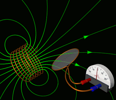
Figure 1
Let’s unpack what Faraday’s Law says by considering the left side of this equation first. The quantity ε is called the electromotive force or emf for short. Contrary to its name, it is not a force in the sense of forces that are measured in units of Newtons. It is more similar to a potential difference that is measured in Volts. The electromotive force is the energy provided per charge to move charges through the loop. Just as the chemical reaction inside a battery serves as the energy source or pump that pushes charges around a circuit, the induced emf serves as the pump that pushes charges in the loop. What’s remarkable, however, is that an emf is present in this loop even without a battery! The changing magnetic flux that we observed in the animation is responsible for inducing this emf in the wire loop to the right because it creates an electric field in the wire that pushes these charges. This electric field exerts a force on the electrons in the loop causing them to move and generate the current that we can measure using the galvanometer.
So, what exactly produces this emf? Let’s look at the right side of the equation to answer this question. (∆ΦB)/∆t represents the rate of change of magnetic flux. This is a quantity that we explored in detail in the previous section. Recall that magnetic flux, ΦB, is the component of the magnetic field parallel to the loop’s area vector multiplied by the area enclosed by a loop. It follows that ∆ΦB would be the change in magnetic flux over some interval of time, ∆t. Thus, the quicker the flux changes, the greater the rate of change of flux. The quantity N simply represents the number of loops of wire. It makes sense that we would multiply the rate of change of flux by N since each loop can be thought of as having its own flux through it. The negative sign indicates that the induced emf will oppose the change in magnetic flux, as described by Lenz's law. In other words, it tells us the direction of the emf (and thus the direction of the current) generated in the loop of wire. The entire next section will focus on Lenz’s Law and determining the direction of this induced emf.
Let’s consider an example to illustrate how Faraday’s Law can be applied to determine an induced emf and induced current in a wire.
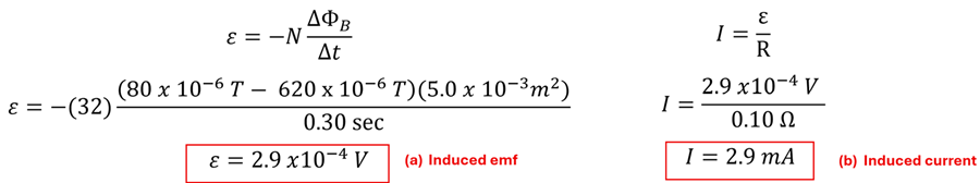
Example 1: Finding the Induced EMF and Induced Current
Problem: A solenoid made of 32 loops of wire is connected to a galvanometer as shown. The wire and galvanometer have a total resistance of 0.10 Ω. Each loop of the solenoid encloses an area of 5.0 x 10⁻³ m2. As a magnet is pulled away from the solenoid, let’s assume the magnetic field through these loops decreases steadily from 620 µT to 80 µT in 0.30 seconds. Find the (a) induced emf and (b) the induced current during this interval.

Solution: (a) Applying Faraday’s Law to find the induced emf in the loop we find that = 2.9 x 10⁻⁴ V. (b) By Ohm’s Law, , we find the average induced current over this time to be = 2.9 mA.
You might have noticed here that we used the term induced emf in the loop as opposed to across the loop, the word that we were careful to use when we described voltage or potential difference in Lesson 1 of Electric Circuits. You might also be thinking, “We wrote Ohm’s Law as I=∆V/R back in that same chapter. Why can we now write Ohm’s Law as I=ε/R?” These are great questions. Let’s briefly explore the similarities and differences between in the induced emf and voltage next.
Understanding Induced EMF and Voltage
How is emf different from voltage? After all, both are measured in Volts, and both are responsible for pushing charges through wires. Truth is, they are very similar. Let’s put them side by side, however, to see how they are similar and how they are different.
| Feature |
Electromotive Force (emf) |
Voltage (potential difference) |
| Symbol |
ε |
∆V |
| Units |
Volts |
Volts |
| Role |
Supplies Energy |
Uses/Transfers Energy |
| Source or Result |
Source: Changing magnetic flux through loop or chemical reaction in batteries |
Result: Circuit elements (resistors, etc) have potential difference across them |
| Measured |
By touching terminals of source when no current is flowing |
Across any two points in circuit when current is flowing |
While both relate to electric potential, emf is the source (such as a battery or changing magnetic flux through a wire loop) of a potential difference, and potential difference is the result that can be measured across a particular circuit element. In essence, emf is the property of a source that creates a separation of charge. Potential difference is merely the difference in electrical potential between two points in a circuit. Think of emf as the water pump that pushes water (charges) through pipes (wires). Potential difference, then, is like the water pressure drop measured across a filter or valve (resistor). In the case of electromagnetic induction, we say that the rate of change of magnetic flux induces an emf since it is the source of the energy supplied to charges. The result of this emf is that a potential difference will now exist across a resistor (or other circuit element) in the circuit.
Motional EMF
We learned in the previous section that there are three ways that we can change the flux through a loop—we can change the magnetic field, the area of the loop, or angle between the field and the area vector of the loop. We explored changing the magnetic field in Example 1 above. Changing the area or changing the angle will also produce an emf. This is sometimes called a ‘motional emf’ since we can change the area and angle by moving parts of the loop itself. Let’s explore a motional emf through a couple examples.
Example 2: Changing Area
Problem: Two parallel conducting rails a distance L apart are immersed in a magnetic field B that points into the page. The two parallel rails are connected on the left side with a resistor of resistance R. A conducting bar rests on top of the parallel rails as shown. A student pulls the conducting bar to the right at a constant velocity v. Derive an expression in terms of B, L, and v for the magnitude of the induced emf in the expanding rectangular loop formed by the rails, conducting bar, and resistor.

Solution: We can see that as the conducting bar is pulled to the right the area enclosed by the closed loop increases. This results in a change of flux in time ∆t. This increase in area can be represented as ∆A = ∆x L. Recalling that v = ∆x/∆t, we find an expression for the magnitude of the induced emf to be B v L.

While this may seem like a unique situation to study, physicists are fond of analyzing such a situation as it is perhaps one of the simplest ways to generate a current in the loop. If the resistor were a light bulb, this is—at least in theory—an incredibly simple way to light a light bulb by merely pulling a metal bar along two rails!
Example 3: Square Loop Moving into and out of a B-Field
Problem: A square loop of wire (20.0 cm x 20.0 cm) is pulled with a constant velocity of 10.0 cm/s into and out of a magnetic field of 0.50 T as shown. The wire loop has a total resistance of 0.2 Ω. (a) During what time intervals is a current induced in the loop? (b) What is the magnitude of the induced current during these intervals?
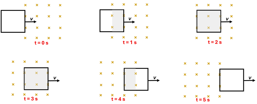
Solution: (a) We recognized in the previous section that it is from 0 to 2 seconds and from 3 to 5 seconds that the magnetic flux is changing. Thus, it is during these two intervals that an emf would be induced in the wire loop and thus an induced current would be present. (b) To find the magnitude of this induced current, let’s first find the magnitude of the induced emf. There are two approaches that we can take—either starting with Faraday’s Law itself or using the result of the motional emf equation derived in Example 2. You’ll see that both approaches yield the same induced emf. We can then find the magnitude of the induced current by simply dividing this induced emf by the resistance of the loop.

Applications of Faraday's Law
Does Faraday's Law have any practical use? Absolutely! Regenerative braking in hybrid and electric cars, wireless chargers, and how the electricity is generated to power your computer right now are just the beginning of hundreds of applications that you may experience as applications of Faraday’s Law. We will explore the physics behind these in greater detail in the next lesson on Generators and Power Transmission. For now, we can appreciate that there are many devices that we use everyday that work because a changing magnetic flux induces an emf (and thus a current) in an electrical loop that does not need a battery to power it.
Before we explore the workings of generators and power transmission, however, it will be important for us to understand the direction of the induced emf (and thus the current). The reason this is so important to understand is that it will allow these applications to make sense in terms of the conservation of energy. So, to make sense of the direction of the induced emf and the reason for the minus sign in Faraday’s Law, we’ll explore an important concept called Lenz's Law. That’s where we’re going next.
Check Your Understanding
Use the following questions to assess your understanding. Tap the Check Answer buttons when ready.
1. A piece of thin wire is wrapped into three loops that form a rectangular shape as shown below. The two ends of this wire are connected to form a closed loop. The wire has a resistance per length rating of 0.0020 Ω/m. The wire loop is now immersed in a magnetic field that is decreasing with time. When a student starts a stopwatch, the magnetic field sensor recorded a B-field of 8.0 mT. When the stopwatch read 0.40 seconds, the magnetic field sensor reported a B-field of 2.0 mT.

(A) What is the magnitude of the average induced emf during this time interval?
(B) What is the magnitude of the average induced current during this same time?
Check Part A Answer
Answer: 0.14 V

Check Part B Answer
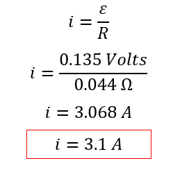
Answer: 3.1 A
The resistance of the entire loop of wire can be found by multiplying its entire length by the resistance per length measured in Ohms/meter. That is, (3 loops)(2·(1.2 m)+2·(2.5 m)) (0.0020 Ω/m) = 0.044 Ω. Ohm’s Law can now be used to find the induced current in the loop.
2. A wedding ring (radius = 1.0 cm, resistance = 3.0 x 10⁻⁴ Ω) is on a technician’s hand 2.0 m to the right of a long, straight wire as shown. The long, straight wire is carrying 20.0 A of current when a power failure occurs. Assume that since the size of the ring is small compared to its distance from the wire, the magnetic flux across the ring’s area at any moment in time is uniform. If the current drops to zero in 15 milliseconds,

(A) What is the magnitude of the induced emf in the ring?
(B) What is the magnitude of the induced current in the ring?
Check Part A Answer
Answer: 4.2 x 10
-8 V
We’ll first need to find the strength of the initial magnetic field in the vicinity of the ring at a distance of 2.0 m from the long, straight wire. We can do this by applying the
B-field equation for a current-carrying wire. Next, we’ll apply Faraday’s Law to calculate the induced emf.
Check Part B Answer
Answer: 140 µA
Applying Ohm’s Law, we find i=(4.2.0 x 10-8 V)⁄(3.0 x 10⁻⁴ Ω=140 μA.). This is a relatively small current. Had this ring been much closer to the wire or had the current in the straight wire been significantly larger, however, the induced current would have been much larger as well. Such a situation could pose a danger to technicians working near equipment where a quickly changing magnetic field may be present.
3. A uniform magnetic field of 2.0 T points upward between two parallel conducting rails as shown. The rails, which are a distance of L=0.80 m apart, are connected by a 5.0 Ω resistor on the left end. A conducting bar, which is always in contact with the rails, is pulled along the two rails with a velocity of 1.5 m/s to the right. Assuming the resistance of rails and movable conductor is negligible...

(A) What is the magnitude of the induced emf in the loop?
(B) What is the magnitude of the induced current through the resistor?
Check Part A Answer
Answer: 2.4 V
From the motional emf problem (Example 2) above we derived the expression ε=BvL for the induced motional emf due to the increasing area of the loop through which the B-field passes. Using this equation, we find ε=(2.0 T)(1.5 m/s)(0.80 m)=2.4 V.
Check Part B Answer
Answer: 0.48 A
Using Ohm’s Law, i = (2.4 V) / (5.0 Ω = 0.48 A.
4. A rectangular conducting loop enters (Position A), moves through (Position B), and exits (Position C) a uniform magnetic field of 0.60 T. What is the magnitude of induced emf in each position if h = 0.40 m, w = 0.60 m, and v = 1.2 m/s?

Check Position A Answer
Answer: 2.9 V
We can use the motion emf equation, ε=BvL, derived from Faraday’s Law. We find ε=(0.60 T)(1.2 m/s)(0.40 m)=0.29 V. If you are wondering how we know that ‘h’ is the value that we substitute in for L, recall from Example 2 that in this derivation we are multiplying the height of the changing area by its width and then dividing by the time over which this change takes place. Since the change in width divided by the time is the velocity of the moving loop, it follows that the height h is the variable that gets multiplied by this velocity. The value ‘w’ in this problem is not necessary for our calculation.
Check Position B Answer
Answer: 0 V
Since there is no rate of change of flux in this position, by Faraday’s Law there will be no induced emf.
Check Position C Answer
Answer: 2.9 V
The reasoning here is the same as that of Part A since we are just looking for the magnitude of the induced emf. It turns out, however, that the direction of the induced emf will be different. To understand the direction of this induced emf, we need to understand Lenz’s Law. This will be explored in the next section.
We Would Like to Suggest ...
Sometimes it isn't enough to just read about it, you need additional practice. Check out the
CalcPad for additional practice problems.